Project 1
I decided to use my architecture studio project as my project for ARCH 653. The basis of my studio project was to find out how the sound levels within a building program can help influence the form of the building.
I took the program spaces and made them into rectangular blocks based off of the square footage that was required of each space. I then determined the sound level that would be generated within each space and that is what generated the height of each program block. The taller the program block is, the louder the space is and vice versa.

From the program blocks, I was able to define floor plates for each program space and used a series of ADA compliant ramps (having no greater than a 1/12 slope) in order to connect the different floor plates.

I then used the same program blocks to help define a roof. The roof curves over the blocks as if it was a blanket being laid over the building. In order to model it, I created a flat curved mass surface using splines and extruding them in order to create one large blanket over the program spaces. I then used the in-place component tool to model roofs based off of that blanketing mass surface.

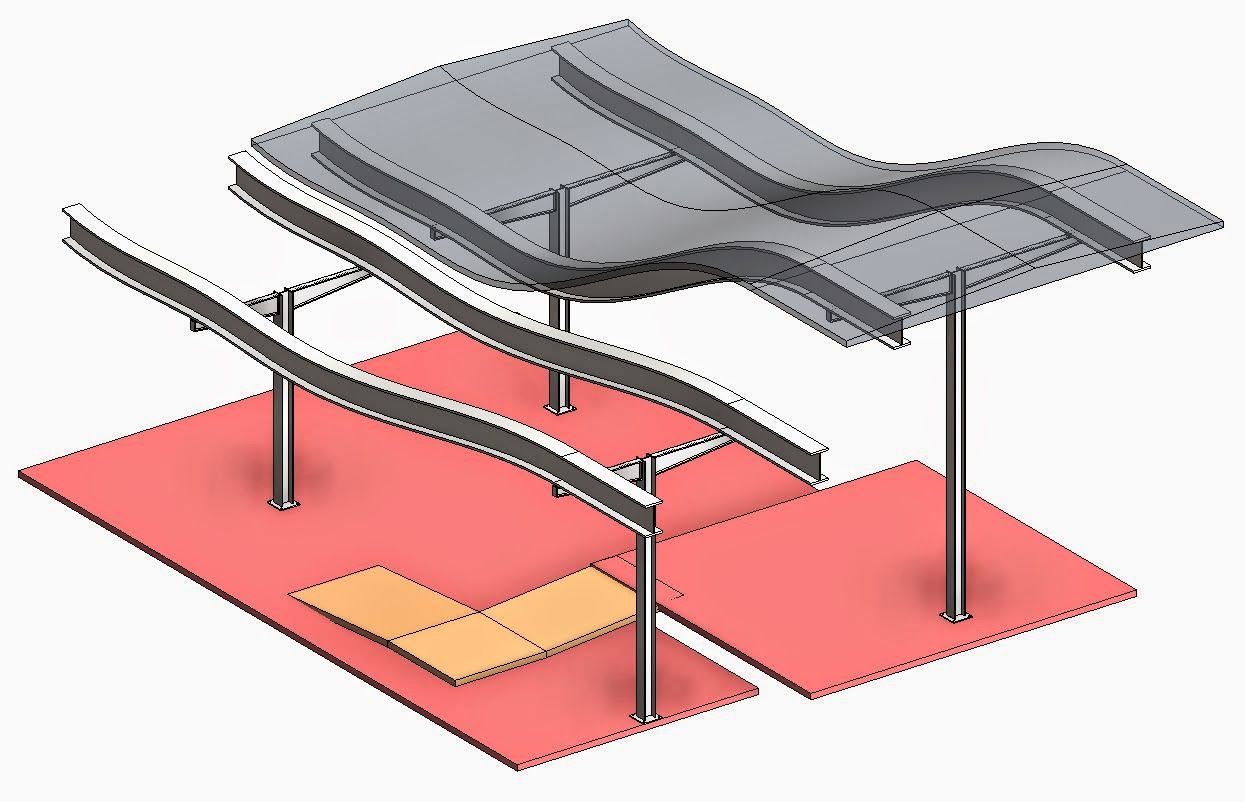
At this point, I needed to begin thinking about the structure and how that would help connect the planer elements at the floor level to the curved elements at the roof level. My solution was to create a series of curved W-Sections that followed the curves of the roofs. These would then be supported by a column-beam assembly that I would model as a parametric family which would be easily modified and replicated.
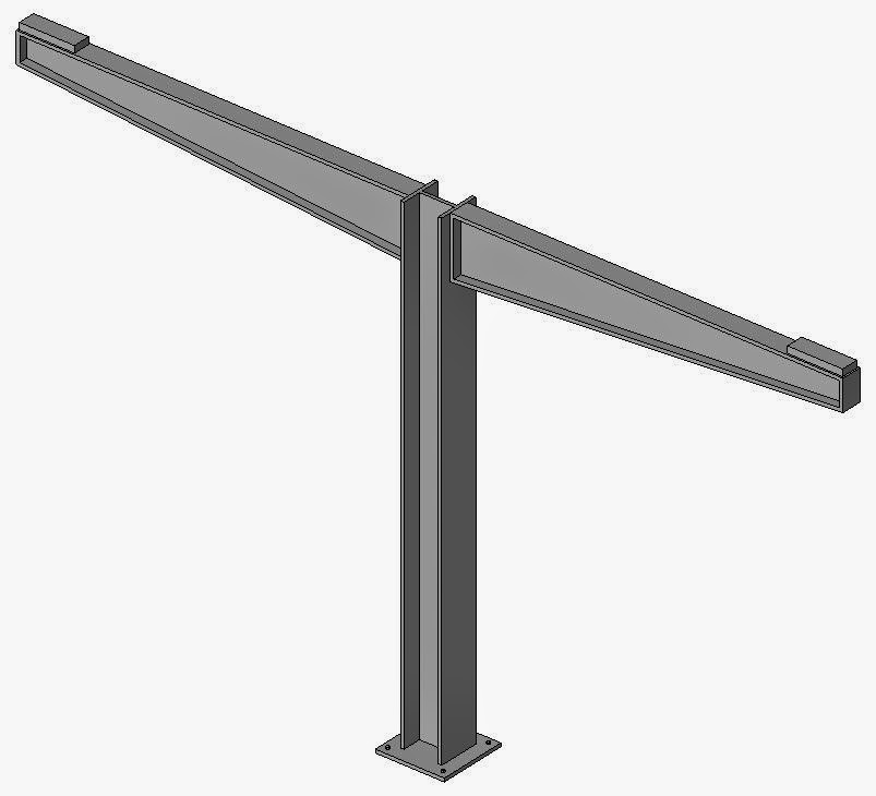
Here is the column-beam family that I created.
In elevation, you can see the reference planes that were used in order to help understand how the model is restrained and what the parameters control.

Here is a list of parameters that helped define the form. The only parameters that would typically be adjusted between instances are the Span Length and the Support Height parameters.

Once I had the floors, roofs and structure in place, I concluded the modeling by enclosing the building. I used typical walls for the exterior of the building but where there were gaps that were created between the roofs, I placed curtain walls in order to allow light to enter into the center of the building. Once can see how this works by looking at the building from a bird's eye view.


Once the building was enclosed, I wanted to create a type of shading mechanism that could follow the exterior of my building. I mass surfaces and created a shading panel within a curtain panel system.

I used reference planes to use as a reference for the shading panels. The reference plans are driven by a single angle parameter that is applied to the opposite ends of the planes. The angles are themselves driven by a formula that uses a user defined value that represents the depth that the shading system covers.

Here are the two parameters that were used and the trig formula that was created.

This is a close up of what the shading system becomes and how it is used in relation to window openings.

Here is a colored interior view to show the character of the interior of the building.

Here is a rendered view of the interior which helps show what the space would look like if it was actually built.

Here is what the building would look like if one was walking up to the entrance.

Video showing the design and modeling process.
CLICK HERE FOR THE YOUTUBE VIDEO
I decided to use my architecture studio project as my project for ARCH 653. The basis of my studio project was to find out how the sound levels within a building program can help influence the form of the building.
I took the program spaces and made them into rectangular blocks based off of the square footage that was required of each space. I then determined the sound level that would be generated within each space and that is what generated the height of each program block. The taller the program block is, the louder the space is and vice versa.
From the program blocks, I was able to define floor plates for each program space and used a series of ADA compliant ramps (having no greater than a 1/12 slope) in order to connect the different floor plates.
I then used the same program blocks to help define a roof. The roof curves over the blocks as if it was a blanket being laid over the building. In order to model it, I created a flat curved mass surface using splines and extruding them in order to create one large blanket over the program spaces. I then used the in-place component tool to model roofs based off of that blanketing mass surface.
At this point, I needed to begin thinking about the structure and how that would help connect the planer elements at the floor level to the curved elements at the roof level. My solution was to create a series of curved W-Sections that followed the curves of the roofs. These would then be supported by a column-beam assembly that I would model as a parametric family which would be easily modified and replicated.
Here is the column-beam family that I created.
In elevation, you can see the reference planes that were used in order to help understand how the model is restrained and what the parameters control.
Here is a list of parameters that helped define the form. The only parameters that would typically be adjusted between instances are the Span Length and the Support Height parameters.
Once I had the floors, roofs and structure in place, I concluded the modeling by enclosing the building. I used typical walls for the exterior of the building but where there were gaps that were created between the roofs, I placed curtain walls in order to allow light to enter into the center of the building. Once can see how this works by looking at the building from a bird's eye view.
Once the building was enclosed, I wanted to create a type of shading mechanism that could follow the exterior of my building. I mass surfaces and created a shading panel within a curtain panel system.
I used reference planes to use as a reference for the shading panels. The reference plans are driven by a single angle parameter that is applied to the opposite ends of the planes. The angles are themselves driven by a formula that uses a user defined value that represents the depth that the shading system covers.
Here are the two parameters that were used and the trig formula that was created.
This is a close up of what the shading system becomes and how it is used in relation to window openings.
Here is a colored interior view to show the character of the interior of the building.
Here is a rendered view of the interior which helps show what the space would look like if it was actually built.
Here is what the building would look like if one was walking up to the entrance.
Video showing the design and modeling process.
CLICK HERE FOR THE YOUTUBE VIDEO
No comments:
Post a Comment