Dynamo with Revit
For Project 2, I wanted to improve upon my first project by using Dynamo as a tool to manipulate the shading family that I created based on the time of day.
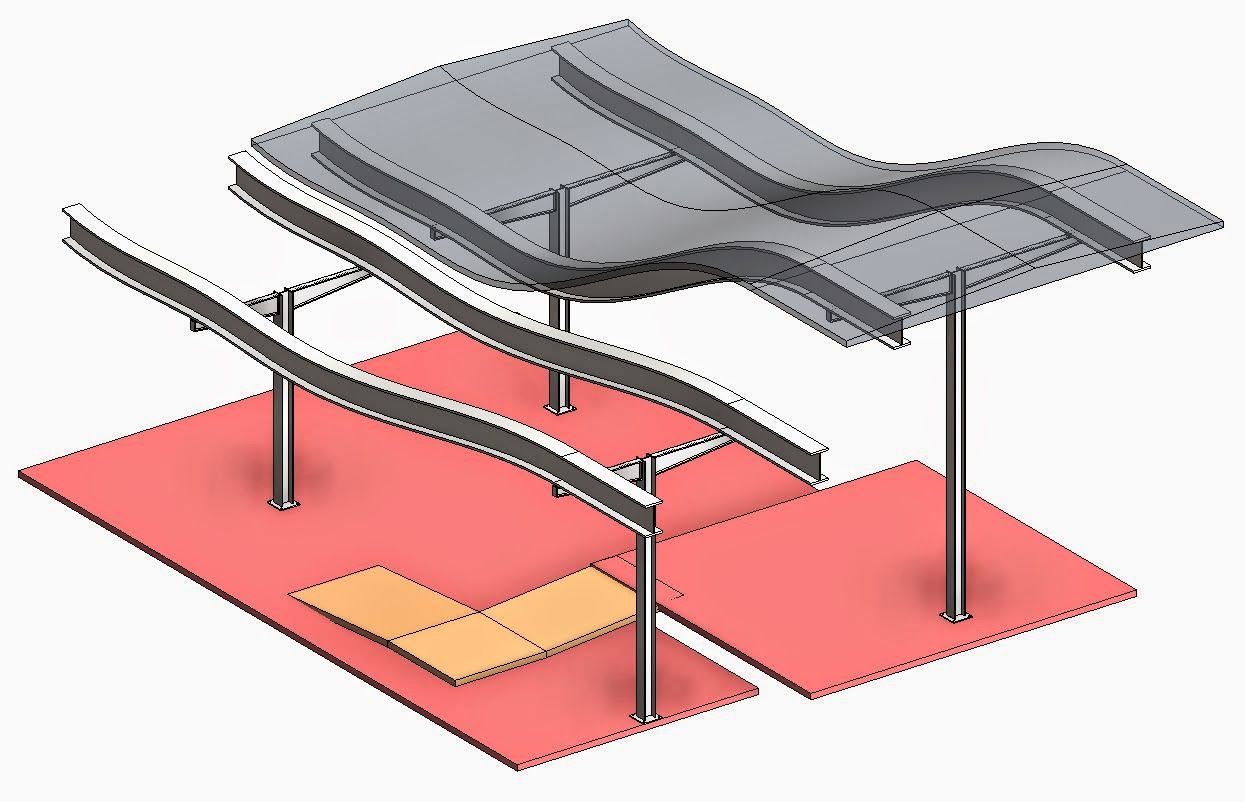
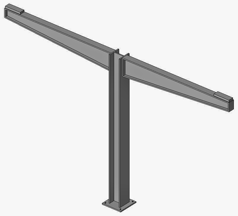
The shading family is the same as it was in the first project. It is created as a curtain panel family with a hinged shade that can be adjusted based on a parameter that controls the angle of the shade hinge.


As you can see, the parameter controls reference planes, on which the geometry is placed. When the angle is adjusted, it uses the angle and a trigonometric function to adjust the reference planes accordingly which then changes the shading form. In this instance, I changed the parameter from 30 degrees to 60 degrees and you can see the change that occurred.

I loaded this family into the main project and created a mass around the perimeter of my building, on which I placed a divided surface and set the surface to this shading panel family.

Here are all of the curtain panels with a different shade angle value to display how this system works along with the shape possibilities of using different angles for the parameter.
The next step was to use visual programming in Dynamo to find a way to control these panels shading angle based on the time of day for system efficiency and interior comfort.

I designed this string in Dynamo to do just that.

This string looks complicated, but it is actually very simple if you examine each major piece of the string.

The first objective was to gather information from the location of the sun in the project. For this example, I was able to find the X - Y - Z coordinates of the sun. You can see the values of each by looking at the "Watch" node.
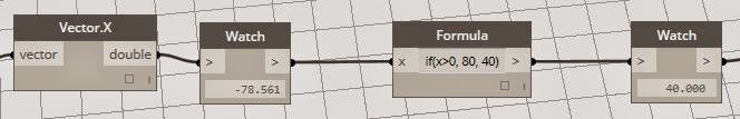
I noticed that as I adjusted the sun location in Revit, the X-value moved from -90 in the morning, to 0 at noon, and then to -90 in the afternoon. I decided that an easy way to adapt this value to my shading parameter was to use a formula that says,
"If the sun X-Value is in between 90 and 0 (morning sun) then the shade will be open. If that is false (or in between 0 and -90, which is afternoon sun), then the shade will close."
In the formula, the 80 and 40 values will be presented as the new values for the parameter "Shade Angle". In this case, since the sun is in the afternoon position, the Shade Angle will be set to 40 which will close the shading to keep the hot sun out of the building.

The value that comes out of the formula is simply a number. However, the Shade Angle parameter is actually a degree value. For this reason, it is necessary to convert this number into that angle type by using a "Degree to Radians" node.
Next, we have to select the actual panels that we want to apply this Dynamo string to.

This is where things got interesting. In order for me to edit a shading panel, I would have to open the mass editor. However, when I had the mass editor open, I could not apply the Dynamo string at the same time. The solution that was found (with a little help from Professor Yan!) was to take the mass and create a separate parameter on the mass itself (which is basically just a way to forward the parameter from the shading family to be editable on the in-place mass family). So, once this Shade Angle parameter was set to the Shade Angle Mass parameter, I could close out of the Mass Editor and continue working on my string.
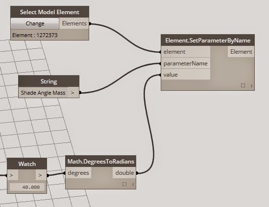
Now that the shading panels are attached to the In-Place Mass, I could then select the In-Place Mass containing all of the Shading Panel instances from inside Dynamo. I used a node in Dynamo that allowed me to change the parameter of the object that I chose in Revit. Using this, I could state which Parameter I wanted to made editable, and then connect the resultant value from my sun formula into the "SetParameterByName" node to set the new parameter value.
Once this string was finished, I could apply it to my project.
As you can see here, the sun has been adjusted in Revit to be set to 8:45 AM.

Here, you can see that all of the shades opened up and the Shade Angle parameter has adjusted accordingly.


Likewise, I then set the sun in Revit to its location at 4:15 PM.

In the same fashion, the parameter has adjusted accordingly which has closed the shades.


For Project 2, I wanted to improve upon my first project by using Dynamo as a tool to manipulate the shading family that I created based on the time of day.
The shading family is the same as it was in the first project. It is created as a curtain panel family with a hinged shade that can be adjusted based on a parameter that controls the angle of the shade hinge.
As you can see, the parameter controls reference planes, on which the geometry is placed. When the angle is adjusted, it uses the angle and a trigonometric function to adjust the reference planes accordingly which then changes the shading form. In this instance, I changed the parameter from 30 degrees to 60 degrees and you can see the change that occurred.
I loaded this family into the main project and created a mass around the perimeter of my building, on which I placed a divided surface and set the surface to this shading panel family.
Here are all of the curtain panels with a different shade angle value to display how this system works along with the shape possibilities of using different angles for the parameter.
The next step was to use visual programming in Dynamo to find a way to control these panels shading angle based on the time of day for system efficiency and interior comfort.
I designed this string in Dynamo to do just that.
This string looks complicated, but it is actually very simple if you examine each major piece of the string.
The first objective was to gather information from the location of the sun in the project. For this example, I was able to find the X - Y - Z coordinates of the sun. You can see the values of each by looking at the "Watch" node.
I noticed that as I adjusted the sun location in Revit, the X-value moved from -90 in the morning, to 0 at noon, and then to -90 in the afternoon. I decided that an easy way to adapt this value to my shading parameter was to use a formula that says,
"If the sun X-Value is in between 90 and 0 (morning sun) then the shade will be open. If that is false (or in between 0 and -90, which is afternoon sun), then the shade will close."
In the formula, the 80 and 40 values will be presented as the new values for the parameter "Shade Angle". In this case, since the sun is in the afternoon position, the Shade Angle will be set to 40 which will close the shading to keep the hot sun out of the building.
The value that comes out of the formula is simply a number. However, the Shade Angle parameter is actually a degree value. For this reason, it is necessary to convert this number into that angle type by using a "Degree to Radians" node.
Next, we have to select the actual panels that we want to apply this Dynamo string to.
This is where things got interesting. In order for me to edit a shading panel, I would have to open the mass editor. However, when I had the mass editor open, I could not apply the Dynamo string at the same time. The solution that was found (with a little help from Professor Yan!) was to take the mass and create a separate parameter on the mass itself (which is basically just a way to forward the parameter from the shading family to be editable on the in-place mass family). So, once this Shade Angle parameter was set to the Shade Angle Mass parameter, I could close out of the Mass Editor and continue working on my string.
Now that the shading panels are attached to the In-Place Mass, I could then select the In-Place Mass containing all of the Shading Panel instances from inside Dynamo. I used a node in Dynamo that allowed me to change the parameter of the object that I chose in Revit. Using this, I could state which Parameter I wanted to made editable, and then connect the resultant value from my sun formula into the "SetParameterByName" node to set the new parameter value.
Once this string was finished, I could apply it to my project.
As you can see here, the sun has been adjusted in Revit to be set to 8:45 AM.
Here, you can see that all of the shades opened up and the Shade Angle parameter has adjusted accordingly.
Likewise, I then set the sun in Revit to its location at 4:15 PM.
In the same fashion, the parameter has adjusted accordingly which has closed the shades.
Below is the YouTube video of my Final Presentation for Project 2